Status Scope of services. Nothing on this site is a record of completed work.
Practice Steel & fabrication engineering
Steel detailing
Shop drawings, erection drawings, CNC files, bolt lists and advance bills of material, produced from a model the shop can build from without interpreting it.
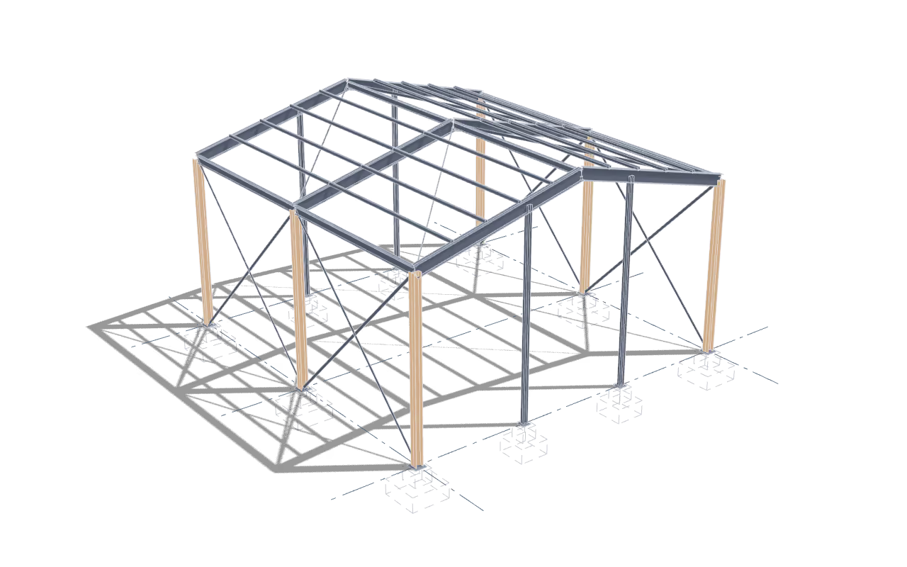
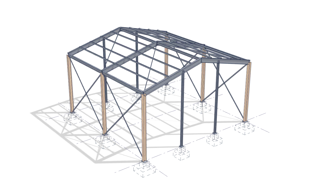
Detailing is the stage where an abstraction becomes a part with a length, a hole pattern and a mark. It is also the stage that gets blamed for rework, usually fairly, because it is where an ambiguity that has been travelling down the chain finally has to be resolved into a dimension.
The questions that cause rework, asked early
Most detailing errors are not drafting errors. They are decisions taken by the detailer because nobody else had taken them: an assumed bolt grade, an assumed camber, an assumed edge distance at a skewed connection. Those are raised as questions against the drawing rather than resolved silently, and the answer goes into the model so that the same question cannot be answered differently on the next sheet.
What the shop actually receives
A shop does not build from a drawing alone. It builds from a package — drawings, CNC data, a bolt list it can order against, and a bill of material it can buy from before the drawings are approved. Advance bills matter more than they look: on a job with long-lead sections, the difference between ordering at week two and week six is the difference between a schedule that holds and one that does not.
Three packages come out of the same model, and each puts something different on a sheet. The frame carries piece marks, assembly logic and the shop welds. Miscellaneous steel — stairs, handrail, platforms, grating, embeds and supports — carries the fit: every connection marked shop-fit or field-fit, the slotted or oversize holes that give a field-fit joint its movement, and the tolerance each one is there to absorb. Joists and deck carry the placement plan: the bridging lines, bolted or welded, marked where they run; every concentrated load dimensioned to the nearest panel point rather than to the grid; and every deck opening set out against the flutes, with its trimming angles detailed as marked pieces rather than noted as a requirement. Steel and fabrication engineering sets out what each of those packages is engineered against.
Which code the drawings are produced to is set by where the steel is erected, not by where it is detailed. Standards sets out which standard governs where.
Deliverables, standards and what you supply
- What you receive
- Shop drawings — assembly and single-part
- Erection drawings, sequenced the way the frame goes up
- CNC files for the shop machines that will cut and drill the material
- Bolt lists by assembly and by shipment
- Advance bills of material for early procurement of long-lead sections
- Miscellaneous steel details: stairs, handrail, platforms, grating, embeds and supports
- Joist and deck placement plans, with bridging lines and every deck opening marked
- The detailing model, in its native format and as IFC
- What you supply
- Approved design drawings and the design basis
- Connection design, or the authority to have it produced here
- The fabricating shop's preferences: hole and slot sizes, weld access, piece size and weight limits, paint marks
- The erection sequence, or the constraints that set it
- The project specification and any client-specific drawing standard
- Checked against
- AISC 303
- AISC 360
- AWS D1.1
- EN 1090-2
- IS 800
Continuous line: Seimora’s scope Dashed line: By others
Which packages a job’s files can be exchanged with, and in what form, is set out once on the standards page.
- Title
- Shop drawing, C1
- Number
- DEMO-SEI-ZZ-XX-DR-S-0101
- Revision
- P01
What arrives, and what leaves
- Arrives from
- BIM & digital delivery
A clash-reviewed model with grids, levels and interfaces resolved goes to detailing, which means the detailer is not the person discovering that a brace lands in a duct.
- Hands on to
- Connection design
Member geometry, end reactions and the joint list go to connection design; the resolved connections come back into the same model before any drawing is issued for fabrication. The loop closes in the model, not in a markup.
Start with this work
Send the model or the drawing set and say which of it you want. A single page of scope is a normal way to start; the other practices are there if the job needs them later.