Status Scope of services. Nothing on this site is a record of completed work.
Structural engineering
Framing schemes, member sizing and design calculations to the governing code, in steel and in the concrete, masonry, light-gauge and timber around it.
- A Set up the jobDesign basis: code, load cases, materials, criteria
- B Qualify the inputsAssumption list against the layouts and loads supplied
- C Produce and checkFraming scheme, member sizing, design calculations
- D Get it approvedGeneral arrangements and connection design criteria, for review
- E Issue and supportThe design set at its issued revision, and the analysis model
Design is where the cost of a structure is decided. A scheme that is efficient in the analysis and awkward in the shop spends in fabrication what it saved in the model, so the decisions on this page — member repetition, connection types a shop can weld without a bespoke procedure, splice positions that suit how the frame is erected — are taken against how the structure gets built and not only against how it is analysed.
The bands below are the materials and elements an engagement here can cover. Each says what the work is done from and what leaves it.
Two things a structural engineer is asked for are deliberately not on this page. Industrial structures and specialty structural engineering — racks, towers, rooftop and platform steel, solar support, lifting schemes and water structures — are canonical under industrial and specialty structures, because what governs them is a load no building code supplies.
The design basis
Every number downstream depends on a small set of decisions taken at the start: which code governs, what the loads are and where they come from, what grades of material are assumed, and how much the structure is allowed to move. Those decisions are written down as a design basis — governing code and any local amendment, load cases and combinations, material grades, deflection and drift limits, and the assumption made wherever information was missing — and the basis is issued with the calculations rather than left implicit inside them. A reviewer can then check a result against its assumption instead of reverse-engineering the assumption out of a model. Where you already have an engineer of record, the design basis is theirs and this work sits inside it. Who may apply a seal to a drawing or a calculation, and what a jurisdiction grants and to whom, is set out once under licensure, on the standards page.
Structural steel
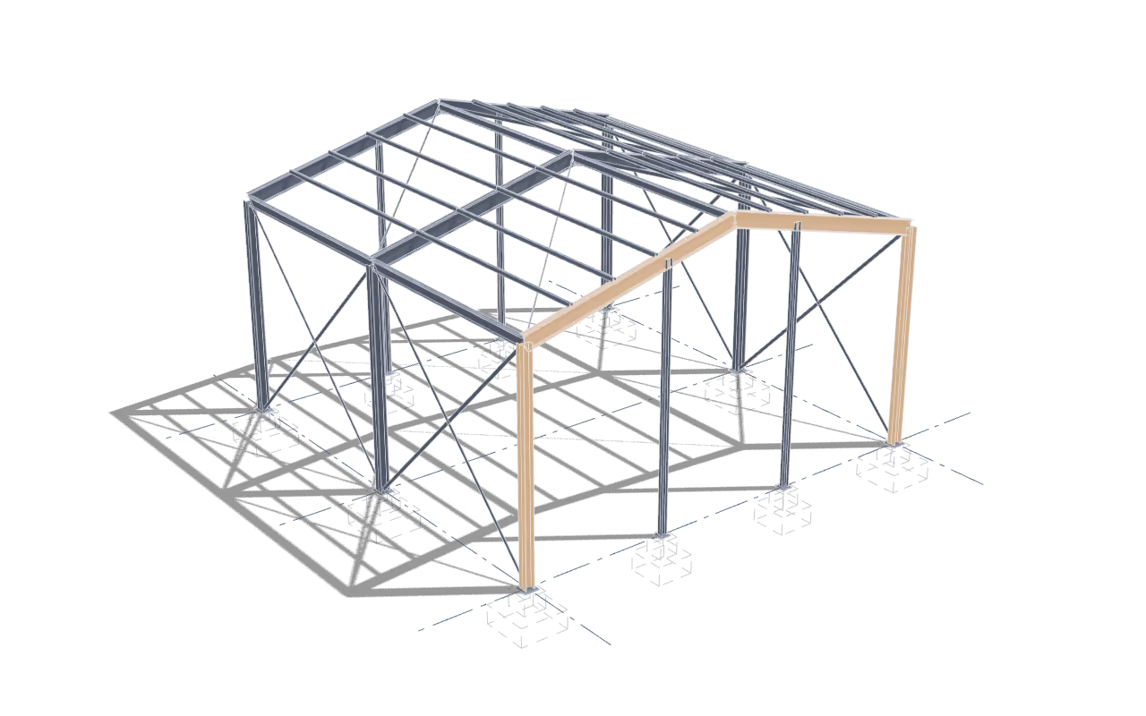
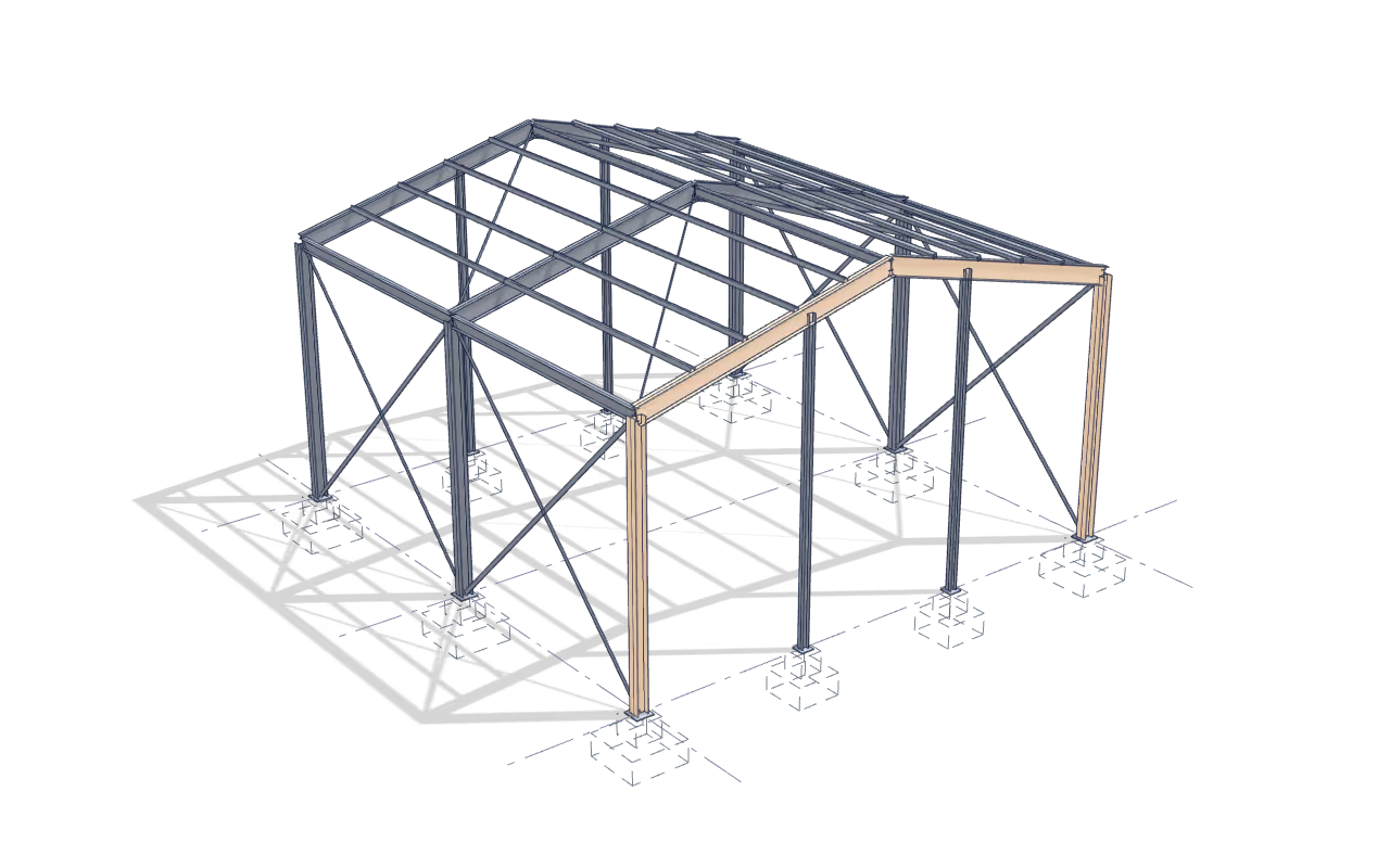
Steel framing to AISC 360, Eurocode 3, IS 800, BS 5950 or AS 4100, whichever the project specification names — the matrix on the standards page says which document governs where. The work is member sizing and the stability system: bracing layout or moment frames, the drift limit the cladding and the lift installation can tolerate, second-order effects, and the serviceability cases that govern a long-span floor well before strength does. Sizes are set with fabrication in view — section repetition across bays, splice positions at a length a truck and a crane can take, and connection types a detailer can develop without a bespoke welding procedure.
Reinforced concrete
Concrete here is the part a steel frame lands on or hangs from: pile caps and pad footings, grade beams, ground and suspended slabs, cores and shear walls, and the embed plates, anchor rods and cast-in channels that carry a steel reaction into concrete. What leaves the band is reinforcement arrangements, embed and anchor layouts with the forces they were sized for, and the bearing and breakout checks at the points where the two materials meet. No concrete code is published on this site — see Pending confirmation below — so each check states the demand, the assumed concrete strength and the reinforcement provided rather than citing a clause.
Masonry
Masonry is designed as part of the frame rather than beside it: load-bearing walls and piers, infill and veneer panels, and the lateral support those panels need. The questions that govern are out-of-plane wind on the panel, the tie and anchor pattern back to the frame or the slab edge, bearing and lintel spans over openings, control and movement joint positions, and the differential movement between a masonry skin and a steel frame that causes most of the cracking later blamed on workmanship. The output is wall and lintel schedules, anchorage layouts, and joint positions marked on the general arrangement.
Light-gauge steel
Cold-formed framing: load-bearing stud walls, infill walls spanning between floors, joists and roof trusses, and the cold-formed secondary members — purlins, girts, eaves beams — that carry cladding into the primary frame. What governs is the deflection limit the cladding system can take, web crippling at bearings, bridging and bracing of slender sections, and the screw, clip and slide-connection details that let a stud wall move with the structure instead of taking load from it. Panel schedules, stud and track sizes and connection details leave this band; as with concrete, the checks state the section, the demand and the limit used.
Wood and mass timber
Timber is engineered here both as a structural material and as an interface. Glulam and cross-laminated floors and roofs, timber framing, and — more often — the steel-to-timber connection: a bearing, a knife plate, a self-tapping screw group or a concealed hanger, sized for a material that moves with moisture and is weakest across the grain. The work covers panel spans and layups, vibration and deflection under service loads, fire resistance by charring depth where the specification asks for it, and the shrinkage and swelling allowance at every interface with steel or concrete.
Foundations and retaining structures
These two are one band because they are read from the same document: the geotechnical report the project supplies. No site investigation is carried out here and no geotechnical parameter is produced here — allowable bearing pressure, settlement limits, the soil and groundwater profile and lateral earth pressure coefficients come from your geotechnical engineer, and they are named as inputs in the calculations so a reviewer can see which parameter a result rests on. On that basis: pad, strip and raft footings; pile caps and pile group layouts against the capacities that report gives; and retaining and basement walls checked for overturning, sliding, bearing and global stability, with the surcharge and drainage assumptions stated beside the result.
Stair systems
Stairs, landings, guarding and handrails as a structural package rather than an architectural detail left to the shop. The work is the stringer or spine-beam span, the reactions the stair puts into the primary frame and into the floor edge at every landing, the uniform and concentrated live loads and the guard and handrail loads the specification calls for, vibration and lateral sway on a long flight, and the fixing detail at top and bottom that lets the stair take frame movement. What leaves is a stair general arrangement, member sizes, reaction schedules for the supporting structure, and the connection criteria the detailer works to.
Temporary structures
Temporary works are designed to the load case they actually see, which is rarely the in-service one. Erection stability and the bracing sequence — which frames stand on their own and which need a guy or a temporary brace until the diaphragm is complete — plus shoring and back-propping, falsework and formwork support, edge protection frames, and lifting checks on a member as it hangs rather than as it sits. Each scheme states the erection sequence it is valid for, because a temporary design that does not name its sequence is a calculation for a different job. What leaves is the scheme, the member and bracing sizes, and the removal conditions the design depends on.
Connection and anchorage design
Connections are engineered on this practice's terms — design forces, or the percentage of member capacity a connection must develop, fixed in the design basis — and worked out in full one level down. Connection design is the canonical page for it: the calculations, the sketches and the schedules, checked against the governing code. What belongs here is what the frame requires of a connection before anyone draws one: the design forces, the anchorage into concrete at every base plate and embed, and the moment connections the stability system depends on.
Pending confirmation
Each of these is held until a fact is confirmed, and named here rather than written around.
HELD — NOT PUBLISHED
- The code a reinforced concrete, masonry, light-gauge or timber element is designed to. Every code published on this site is a steel code, so the bands for those materials describe the work, state what was assumed and name no code until the owner confirms which apply.
- Licensure and sealing in any particular jurisdiction. A licence is granted by a jurisdiction to an individual; no jurisdiction is claimed anywhere on this site and no coverage map is published, and what that means for a submission is set out once on the standards page.
Deliverables, standards and what you supply
- What you receive
- A design basis: governing code, load cases and combinations, material grades, deflection and drift criteria
- Framing scheme and member sizing, set out on the architectural grid you supply
- Design calculations, each stating the load path and the assumption it rests on
- General arrangement drawings
- A connection design criteria schedule: design forces, or the percentage of member capacity a connection must develop
- The analysis model, exported in a format your engineer can open
- What you supply
- Architectural layouts, grids and levels
- Loading criteria, or the standard you want them derived from
- The governing code, and the jurisdiction the structure is built in
- The geotechnical report, where foundations or retaining structures are in scope
- Foundation and substructure interface information
- The project specification, if one exists
- Checked against
- AISC 360
- Eurocode 3
- IS 800
- BS 5950
- AS 4100
Continuous line: Seimora’s scope Dashed line: By others
Which packages a job’s files can be exchanged with, and in what form, is set out once on the standards page.
Continuous line: Seimora’s scope Dashed line: By others
- Title
- Framing scheme, member sizing, design calculations
- Number
- DEMO-SEI-ZZ-XX-CA-S-0003
- Revision
- P01
What arrives, and what leaves
- Arrives from
- Architecture & design support
The coordinated set goes to structural engineering at a stated revision — grids, levels, openings and the interface each party was given — so a framing scheme is set out on a layout that has been reconciled rather than on the last drawing anybody happened to issue.
- Hands on to
- BIM & digital delivery
The analysis model, the member sizes and the design basis go to BIM and digital delivery, so the coordination model is built on a fixed scheme rather than an assumed one.
- Hands on to
- Steel & fabrication engineering
General arrangement drawings, the member schedule and the connection design criteria go to steel and fabrication engineering, so detailing starts from stated forces rather than from an interpretation of them.
Pages under this practice
- PE/SE stamping and code compliance
Compliance review against the governing standard, and stamping arranged against the licensure the jurisdiction reviewing the drawings requires.
- Connection design
Connection calculations, sketches and schedules, checked against the governing code and against what the shop selected for the job can actually fabricate.
What this practice does not do
Structural engineering here designs, calculates and documents; it does not seal, and it does not take the engineer of record's responsibility for a structure — sealing is a licensed act performed by an individually licensed engineer, and the engineer of record is the licensed party you engage for that role.
Start with this work
Send the model or the drawing set and say which of it you want. A single page of scope is a normal way to start; the other practices are there if the job needs them later.