Status Scope of services. Nothing on this site is a record of completed work.
Steel & fabrication engineering
Detailing, connection design and the calculations a fabrication package carries, produced so a shop can build from them without interpreting them.
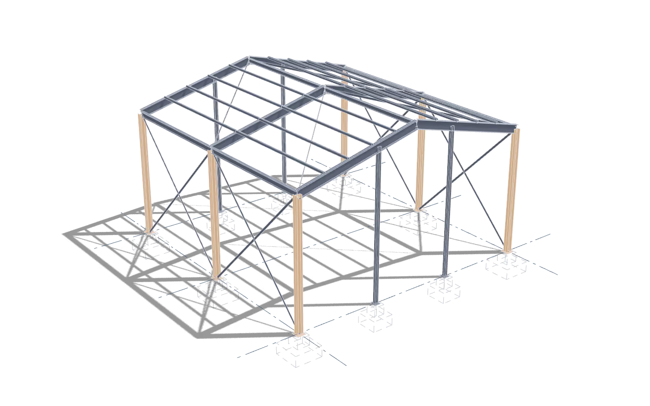
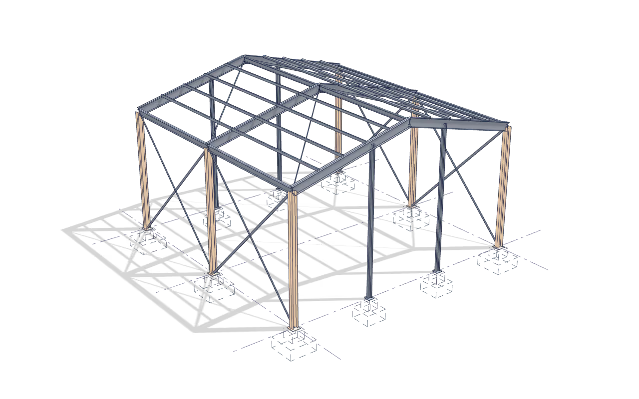
- A Set up the job, a phase this practice does not act inDetailing starts from a design set somebody has already approved, so there is nothing for this practice to set up before one exists.
- B Qualify the inputsDetailing basis: the approved set, the forces, the shop's standards
- C Produce and checkShop and erection drawings, connection calculations
- D Get it approvedThe submittal, and the revision that answers its comments
- E Issue and supportRelease packages by lot, with the inspection and test plan
A fabrication package is read by people who are not engineers. A fitter reads a single-part drawing at a bench, a machine reads a CNC file, a storeman reads a bolt list, and a crew on a site reads an erection drawing in weather. Each needs the same decision resolved the same way — and it is resolved once, in the model, or it is resolved four times and three of those are wrong.
The bands below are what an engagement here can cover. Each says what the work is done from and what leaves it.
The detailing basis
Detailing is the first stage with nothing left to assume, so it starts by fixing what it is allowed to assume. Written down before the first assembly is drawn: which issue of which drawing set is being detailed and its date, the governing code and the specification, the shop's own standards — hole and slot sizes, weld access, maximum piece length and weight, paint marks — the bolt grades allowed and excluded, camber and fit-up tolerances, and the erection sequence the pieces will be flown in. The point of writing it down is the revision that follows: the assembly drawing, the single-part drawing, the CNC file, the bolt list and the bill of material all come out of one model, so a change reaches all five of them or it reaches none, and a drawing corrected on its own no longer matches the part the machine cut. How a revision is issued, marked and superseded is set out once under revision control.
Structural steel detailing
The primary frame: columns, beams, braces, trusses and girders, with the girts, purlins, sag rods and eaves members that carry cladding into it. The work is turning a member schedule into parts — piece marks, assembly logic, what is welded in the shop and what is bolted in the field, what ships as one piece and what has to be spliced to fit a truck or clear a site gate. Repetition is worth money here: two assemblies differing by a 5 mm hole gauge are two piece marks, two fabrication setups and two things to get wrong on site, and the detailer is the last person who can still merge them. Steel detailing is the page for what leaves — the package, sheet by sheet, and the model it is generated from.
Miscellaneous steel
Stairs, ladders, handrail and guarding, platforms and mezzanines, grating and chequer plate, lintels, embeds, bollards, pipe supports, door and louvre frames — the package priced by the tonne and delivered by the piece. Two things make it harder than the frame rather than easier. Its geometry comes from the architectural drawings while its supports come from the structural ones, and the two sets stop agreeing at exactly the points miscellaneous steel attaches to. And much of it is detailed last and wanted first, because handrail cannot be dimensioned until the stair is set and the stair cannot be set until the frame is plumbed. Detailing it early means deciding which connections are field-fit and saying so on the drawing, rather than discovering it with a crew standing on the landing.
Joist and deck detailing
Open-web steel joists, joist girders, bridging, and the metal deck spanning between them. A joist is a manufacturer's product, sized by the supplier against the loads it is given, so the work here is the placement plan and the loading that plan is made against: uniform and net uplift loads, bridging lines and where bridging has to be bolted rather than welded, and — the one that causes the most trouble — every concentrated load hung from a joist, with its position stated relative to a panel point. A duct hanger at mid-panel loads a chord in bending nobody sized it for, and it surfaces as a question from site months after the joists were rolled. Deck takes the same discipline: sheet layout, side-lap direction, edge angles and pour stops, and openings sized and reinforced on the drawing rather than cut by whoever needs one.
Connection design
Connections are the largest single variable in what a frame costs to fabricate, so they are treated as one subject rather than as a property of each drawing. Connection design is the canonical page for it: the calculations per connection type and load case, the sketches carrying bolt grade, weld size, plate thickness and edge distance, and the schedule keyed to the joint marks in the model. What belongs here is the loop around it — the reactions a connection is designed to and what is done when none was issued, the anchorage into concrete at every base plate and embed, and the rule that a resolved connection goes back into the same model the drawings come out of before anything is issued for fabrication.
Engineering calculations
Not every calculation a fabrication package needs is a connection calculation. A shop asks to substitute a section it already has in stock; a service run needs a hole through a beam web; a piece is too long for the road and has to be spliced where nobody designed a splice; a heavy assembly has to be picked and needs a lifting point that will not fold it. Each of those is a check against the governing code, and what leaves is a written deviation carrying the demand, the assumption and the result — so the change is decided by the engineer of record against a document rather than on a telephone call. Undocumented deviations are how a frame ends up as-built to a design nobody can produce.
Erection drawings
An erection drawing is not a shop drawing with more sheets on it. It is drawn for a crew with a crane, in weather, and it answers different questions: which piece goes up when, which bolts are field bolts and in what size and grade, where temporary bracing stays until the diaphragm closes, and what the anchor rods were set to before any steel arrived. The one that catches people is the shipping list. Pieces have to be loaded in the reverse of the order they are erected, or the crew unloads a truck twice to reach the column it needed first. Anchor rod setting plans are issued early for the same reason: a setting plan issued with the rest of the package is a plan that arrives after the concrete.
Design-assist
Design-assist is fabrication knowledge applied while the design can still change, which is the only time it is worth anything. The questions are budget-level tonnage against two or three framing schemes; whether a braced bay costs less than the moment frame it replaces once the connections are drawn; splice positions set by the crane and the road rather than by the analysis; connection types a shop's own equipment can produce without a bespoke welding procedure; and which sections to release to the mill first, so a long-lead order is not the thing holding the programme. Design-assist produces decisions rather than drawings, and an undocumented decision is a variation later — so what leaves the band is the decision itself: the option taken, the assumption it rests on, and whose call it was. It moves no design responsibility: the engineer of record holds that.
Fabrication coordination
Once drawings are released, the job stops being a drawing problem and becomes a sequence problem — what was released, at which revision, to whom, and what came back. Fabrication coordination is the page for it: release packages by lot or by erection sequence, the inspection and test plan issued with them, and a production status record reconciled against what was released rather than against what was drawn. Seimora operates no fabrication shop, so this is coordination of a fabrication programme against the shop that will build the job, and not the fabrication itself.
Pending confirmation
Each of these is held until a fact is confirmed, and named here rather than written around.
HELD — NOT PUBLISHED
- The document a steel joist, a joist girder or a metal deck is specified against. Every code published on this site governs hot-rolled steel framing, and the joist and deck institutes' documents are not among them, so the joist and deck band states the loads, spans and bearing conditions a supplier's product has to be selected for, and names no document until the owner confirms which apply.
- The certifications a fabrication package can be built under. EN 1090, ISO 3834 and AISC certification are held by a fabricating shop against its own systems and audited at that shop; none is published here as held by anyone, and no facility is named on this site.
Deliverables, standards and what you supply
- What you receive
- Shop drawings, assembly and single-part, to the shop standard you supply
- Erection drawings sequenced to the erection method, with a bolt list per shipment
- Connection calculations and sketches, stating the reactions and the code clauses they were checked against
- A joist and deck placement plan, with the load each joist and each deck opening is specified to
- CNC and fabrication data generated from the same model the drawings are generated from
- An advance bill of material for long-lead sections, issued before the drawings are complete
- A deviation register: every substitution, hole or splice the shop asked for, and what each was checked against
- What you supply
- Approved design drawings and the design basis they were issued under
- Connection design criteria: design forces, or the percentage of member capacity a connection must develop
- The shop's own standards: hole and slot sizes, weld access, piece size and weight limits, paint marks
- The erection sequence, or the site constraints that set it
- The governing code, and the project specification with any drawing standard it calls up
- Checked against
- AISC 303
- AISC 360
- AWS D1.1
- Eurocode 3
- EN 1090-2
- IS 800
Continuous line: Seimora’s scope Dashed line: By others
Which packages a job’s files can be exchanged with, and in what form, is set out once on the standards page.
Continuous line: Seimora’s scope Dashed line: By others
- Title
- The submittal, and the revision that answers its comments
- Number
- DEMO-SEI-ZZ-XX-SH-S-0008
- Revision
- P01
What arrives, and what leaves
- Arrives from
- Structural engineering
General arrangement drawings, the member schedule and the connection design criteria go to steel and fabrication engineering, so detailing starts from stated forces rather than from an interpretation of them.
- Arrives from
- Industrial & specialty structures
The loading basis travels with the package: the general arrangement, the member schedule and the connection design criteria go to steel and fabrication engineering with the operating case each member was sized for, so a detailer proposing a substitution knows which load it has to satisfy.
- Hands on to
- Construction coordination and project controls
The release schedule, the lot breakdown and the production status record go to construction coordination, so the programme is reported against what was released for fabrication rather than against what was drawn.
Pages under this practice
- Steel detailingDEMO-SEI-ZZ-XX-DR-S-0101
Shop drawings, erection drawings, CNC files, bolt lists and advance bills of material, produced from a model the shop can build from without interpreting it.
- Connection design
Connection calculations, sketches and schedules, checked against the governing code and against what the shop selected for the job can actually fabricate.
- Fabrication coordinationDEMO-SEI-ZZ-XX-SH-S-0009
Release packages by lot or erection sequence, the inspection and test plan issued with them, and a production status record reconciled against the release.
What this practice does not do
Steel and fabrication engineering produces the engineering, the drawings and the data a fabricator builds from; it does not fabricate. Seimora operates no shop, holds no fabrication certification and erects nothing — fabrication, coating and erection are carried out by the shop and the erector engaged for the job.
Start with this work
Send the model or the drawing set and say which of it you want. A single page of scope is a normal way to start; the other practices are there if the job needs them later.