Status Scope of services. Nothing on this site is a record of completed work.
Industrial & specialty structures
Racks, towers, rooftop and platform steel, solar support, lifting schemes and water structures — sized against loads a building code does not give.
- A Set up the jobLoading basis: every load case, and the document it was read from
- B Qualify the inputsVendor and process documents, at the revision each was read at
- C Produce and checkFraming and sizing against the operating case that governs
- D Get it approvedThe reaction schedule the vendor and the foundation designer share
- E Issue and supportA scheme statement, with the conditions it is valid under
A building is loaded by the people in it and the weather on it. Most of the structures on this page are loaded by something else: a machine with a duty cycle, a pipe that grows when it gets hot, a module the wind can get underneath, a body of water, a crane picking up more than the structure will ever carry again. The consequence is the same every time. The number that governs the design is not in the code — it is in somebody else's document, at a revision that will change, and the first work is finding out whose.
The bands below are the structure types an engagement here can cover. Each says where its governing load comes from and what leaves it.
The loading basis
Every structure here starts from a set of numbers no building code supplies: an operating weight and where its centre of gravity sits, a thermal movement and the friction it drags through a support, a dynamic factor, a fill height, a pressure coefficient for a shape no table covers. They come from a vendor's general arrangement, a process datasheet, a pipe stress report, a geotechnical report or a wind study — every one of them issued by another party, at a revision. So the loading basis is written first and issued with the calculations: each load case, the document and revision it was read from, the party that issued that document, and, where nothing had been issued, the assumption used and what it would take to confirm it. A structure sized against a superseded datasheet is not a conservative structure. It is a structure sized for a different machine.
Industrial structures
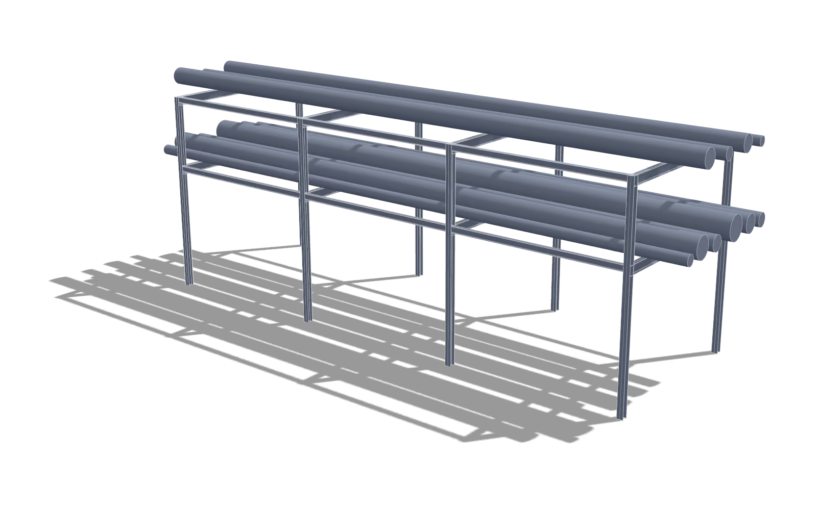
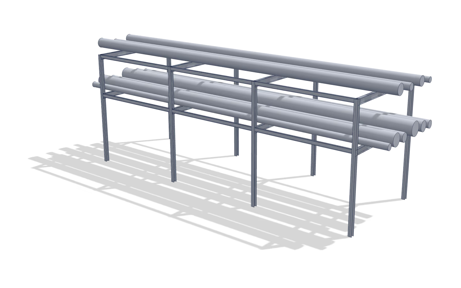
A pipe rack is one bent repeated until the plant ends, so a decision taken in the bent is taken forty times, in both directions. What governs it is rarely the weight of the pipes: it is the anchor and guide forces the pipe stress report gives, the friction a line drags across a shoe as it grows, the empty-against-full case, and the spare tier the process has reserved and nobody has loaded yet. Equipment supports are the same problem over a shorter span — a vessel's operating and test weights, a nozzle's allowable load, the thermal growth of a saddle, a rotating machine's dynamic factor and the isolation its vendor assumed. What leaves is the framing, the member sizes, the anchorage at every base and the reaction schedule. What a plant owner's own specification then adds on top of all of it, and what an audited owner expects to receive, is industrial and process plant.
Towers and masts
A tower is mostly hole, and what fills the hole is wind. The governing case is dynamic rather than static: along-wind response on a slender lattice, vortex shedding across a monopole at a speed well below the design gust, ice on every member in the regions that get it, and the fatigue a million small cycles put through a bolted splice long before one large load threatens it. A guyed mast adds geometric non-linearity and a pretension that is a design parameter rather than a site preference, so the analysis is run at the tensions the mast will actually be erected to. Below ground the case reverses — what sizes a tower foundation is uplift and overturning rather than bearing, both read from the geotechnical report the project supplies. Lighting, marking and airspace clearance are decided by the authority with jurisdiction over the airspace and applied for by the owner.
Rooftop and platform structures
A rooftop structure is mostly a question about a building somebody else designed. Plant screens, dunnage frames, mechanical platforms, walkways and rooftop arrays all put load into an existing frame, so the useful work is as much the check on what is underneath as the design of what goes on top: which members and which foundations take the new reaction, whether the original design left a margin anybody recorded, and what wind uplift does to a screen that is nearly all sail. The capacity of the existing structure is read from its own drawings and calculations where they survive, and from a survey another party captured where they do not; where neither exists, that is stated as a limit on the result rather than assumed away. Vibrating plant brings its own case, because an isolator's stiffness is a design input and a platform tuned near a machine's running speed is a complaint nobody can fix afterwards.
Solar support structures
A module support is the cheapest structure on a site and the one repeated most, which makes an hour spent on its connection detail the best-paid hour on the job and a mistake in it a mistake ten thousand times. What governs is wind on a surface that is mostly edge: pressure coefficients for a tilted array at a row end and at the field boundary, uplift on a shallow-tilt row, and — on a single-axis tracker — the aeroelastic case, where a row stable at every static angle becomes unstable in motion at one of them, which no static coefficient will tell you. Below the module the questions are geotechnical and dimensional: pile embedment and lateral resistance read from the report the project supplies, refusal on rock, terrain slope against the tracker's articulation limit, and the thermal growth of a row long enough for it to matter. What the same repetition does to corrosion protection, to a first-article check and to a freight sequence is the sector's own subject, on energy and renewables.
Lifting, jacking and propping structures
Some of the most heavily loaded structures on a project exist for a week. A crane base or a crane mat carries a load the finished building will never see, at an eccentricity that depends on the boom angle, on ground another party characterised. A lifting beam or a spreader frame is sized to the sling arrangement and the dynamic factor the lift is planned with. A jacking or skidding arrangement has to be stable at every intermediate position, not only at the two ends. A propping scheme for an existing structure is a load path invented for a duration and removed in an order that is part of the design. Each is engineered to an arrangement the lifting or temporary-works contractor issues, and each scheme states the sequence it is valid for. The lift itself — the crane selected, the plan it runs to, the supervision on the day — belongs to that contractor. Erection stability and the bracing sequence of a steel frame are temporary structures, under structural engineering.
Water-retaining and water-related structures
A tank, a basin, a channel or a pump station is governed by a serviceability limit rather than a strength one, because what fails first is tightness: crack width in concrete, weld quality and differential settlement in steel, each deciding the section long before capacity does. The load cases are the ones that get forgotten — full and empty; empty with the water table up, which is buoyancy and will float a structure that is safe in use; a partial fill that is worse on a wall than a full one; the hydrodynamic case where the contents move; and the restraint to shrinkage and thermal movement that cracks a wall nobody has yet put water in. No concrete or liquid-retaining code is published on this site — see Pending confirmation below — so each check states the demand, the properties assumed and the limit it was assessed against rather than citing a clause. Linings, coatings and suitability for a stored liquid are decided by the specification and the product the owner selects.
Pending confirmation
Each of these is held until a fact is confirmed, and named here rather than written around.
HELD — NOT PUBLISHED
- The code a concrete, liquid-retaining or aluminium element is designed to. Every code published on this site is a steel code, so a tank wall, a pile cap, a plinth or an aluminium walkway is described here, checked against a stated assumption, and cited to no clause until the owner confirms which codes apply.
- What role this work takes in a project's temporary-works arrangements. Some jurisdictions place named duties on the party that designs a temporary scheme and on the party that coordinates one, and which of those a scheme produced here is issued under depends on how a project has set itself up. Nothing on this site states that either duty is taken here until the owner confirms it.
Deliverables, standards and what you supply
- What you receive
- A loading basis: each load case, the document and revision it was read from, and the party that issued that document
- Framing schemes and member sizing for the structure in scope, set out on the equipment layout you supply
- Design calculations, each naming the operating case that governs it and the assumption it rests on
- General arrangement drawings, with the reaction schedule the foundation designer and the equipment vendor each work from
- A connection design criteria schedule: design forces, or the percentage of member capacity a connection must develop
- A scheme statement for temporary work: the arrangement, the sequence and the removal conditions the design is valid for
- What you supply
- The equipment layout, and the vendor data each item is supported to: operating and test weights, centre of gravity, nozzle loads and dynamic factors
- The pipe stress report, where a rack or a support carries anchor and guide forces
- The geotechnical report, and the party that produced it
- The wind, snow, ice and seismic criteria, or the standard you want them derived from
- The governing code, and the jurisdiction the structure is built in
- For a temporary scheme: the arrangement the lifting or temporary-works contractor plans to use, and the sequence it is planned for
- For work on an existing structure: its drawings and calculations, or a survey of what is there and the party that captured it
- Checked against
- AISC 360
- Eurocode 3
- IS 800
- BS 5950
- AS 4100
Continuous line: Seimora’s scope Dashed line: By others
Which packages a job’s files can be exchanged with, and in what form, is set out once on the standards page.
Continuous line: Seimora’s scope Dashed line: By others
What leaves
- Hands on to
- Steel & fabrication engineering
The loading basis travels with the package: the general arrangement, the member schedule and the connection design criteria go to steel and fabrication engineering with the operating case each member was sized for, so a detailer proposing a substitution knows which load it has to satisfy.
What this practice does not do
Industrial and specialty structures engineers the structure and states the case each scheme is valid for. It does not plan or supervise a lift, does not operate, test or commission the equipment a structure carries, and deals with no authority on a project's behalf — the lifting contractor, the equipment vendor and the party that holds an application each own one of those.
Start with this work
Send the model or the drawing set and say which of it you want. A single page of scope is a normal way to start; the other practices are there if the job needs them later.